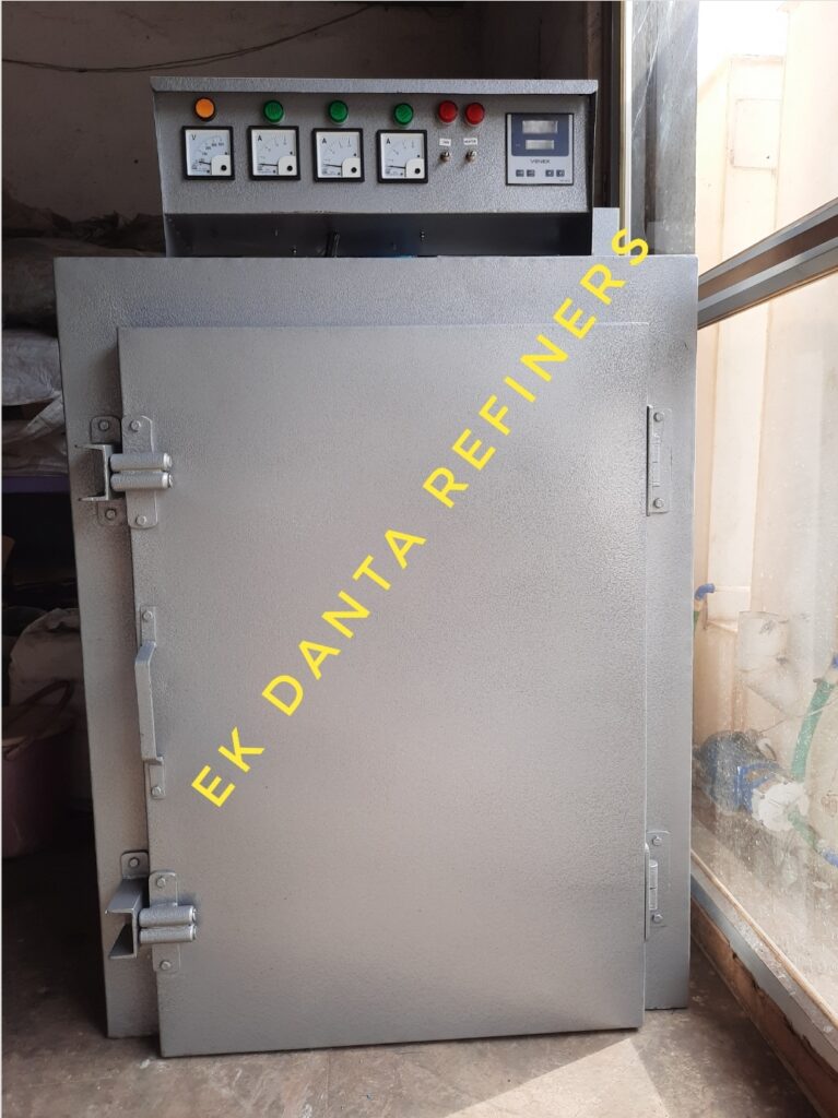
| TECHNICAL DATA | EDR-Annealing | EDR-Copulation | EDR-Melting |
| Max. working temperature | 1150°C | 1150°C | 1150°C |
| Max. temperature at rest | 500°C | 600°C | 700°C |
| Int. Dimensions Silicon Carbide Muffle | 250x250x250mm | 300x300x250 mm | 200x200x200 mm |
| Number of Cupels contained | n.18 diam. 25 mm | n.30 diam. 25 mm | n.9 diam. 25 mm |
| Heating elements | n.6 Ceramic heating elements | n.6 Ceramic heating elements | Metal heating elements |
| Power supply | Three-phase | Three-phase | Single-phase |
| Max. Power | 9 kW | 12 kW | 2.5 kW |
| Overall Dimensions (mm) | 1000x750x1900 mm | 1000x1400x2000 mm | 450x750x850 mm |
| Weight | 150kg |
- Most failures in MLCC are caused by cracking that create shorts between opposite electrodes of the parts. A use of manual soldering makes this problem especially serious for space industry. Experience shows that different lots of ceramic capacitors might have different susceptibility to cracking under manual soldering conditions. This simulates a search of techniques that would allow revealing capacitors that are most robust to soldering-induced stresses. Currently, base metal electrode (BME) capacitors are introduced to high-reliability applications as a replacement of precious metal electrode (PME) parts. Understanding the difference in the susceptibility to cracking between PME and BME capacitors would facilitate this process. This presentation gives a review of mechanical characteristics measured in-situ on MLCCs that includes flexural strength, Vickers hardness, indentation fracture toughness, and the board flex testing and compare characteristics of BME and PME capacitors. A history case related to cracking in PME capacitors that caused flight system malfunctions and mechanisms of failure are considered. Possible qualification tests that would allow evaluation of the resistance of MLCCs to manual soldering are suggested and perspectives related to introduction of BME capacitors discussed.